
The heat source
Identify whether the system removes heat from a product process, production machine, central water loop or building load. This determines how cooling duty and operating time are assessed.
GESON / INDUSTRIAL COOLING MANUFACTURER
SYSTEM ROUTES FOR PROCESS, PLANT AND FACILITY COOLING
GESON designs industrial cooling systems around the heat source, heat-rejection method, fluid conditions and project boundary. Start with the operating environment, then select the appropriate chiller route.
INDUSTRIAL COOLING ROUTES
Industrial cooling should not begin with a nominal capacity number. Use the route that fits the process, utilities and operating environment; the technical proposal then confirms the selected model at defined conditions.
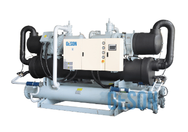
WATER-SIDE HEAT REJECTION
For projects that can support an engineered condenser-water circuit and need the chiller, heat rejection, water quality and pump scope reviewed as one system.
Review for continuous process loads, central chilled-water plants and project-specific water-side conditions.View route ↗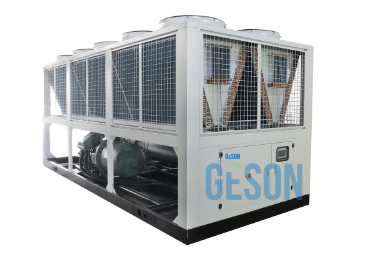
AIR-SIDE HEAT REJECTION
For industrial sites that prefer self-contained outdoor heat rejection without a cooling tower or condenser-water loop.
Review for design ambient, airflow clearance, sound limits, electrical supply and packaged chilled-water scope.View route ↗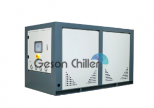
PROCESS-SPECIFIC COOLING
For manufacturing equipment and product processes where the temperature, fluid circuit, operating schedule and heat source define the cooling requirement.
Review for central or compact configurations, water or glycol loops and temperature-sensitive production steps.View route ↗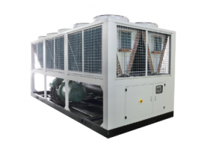
BUILDING AND FACILITY PLANTS
For commercial and institutional chilled-water plants serving air-handling units, fan coils and wider building cooling infrastructure.
Review for building load, operating profile, climate, redundancy, controls and whole-plant interfaces.View route ↗SELECTION COMPASS
The initial project data creates the boundary for an engineering review. It also prevents unsuitable equipment from being compared at different operating conditions.
Identify whether the system removes heat from a product process, production machine, central water loop or building load. This determines how cooling duty and operating time are assessed.
Choose the air-side or water-side route only after checking outdoor conditions, cooling-tower or water availability, maintenance capability, sound and site constraints.
Declare supply and return temperatures, flow, water or glycol concentration, pressure drop and temperature-control needs. These change capacity and pump requirements.
Confirm what is factory supplied and what is provided at site: chiller, pumps, tank, tower, piping, controls, electrical connection, commissioning and service access.
APPLICATION CONVERSATIONS
Each application asks for different process data, equipment interfaces and temperature-control priorities.
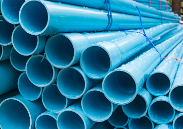
Injection molding, extrusion and forming projects are reviewed around process cycle, heat source, cooling-fluid temperatures, flow and machine count.

Food processing, fermentation, mixing and packaging applications require the process temperature, fluid-side materials, sanitation considerations and operating profile to be defined.

Chemical and pharmaceutical projects must define process compatibility, required temperature range, corrosion exposure, operating schedule and the consequence of a shutdown.

Laser, medical and other sensitive equipment cooling starts with the required stability, heat input, water quality, flow, alarms and service access.
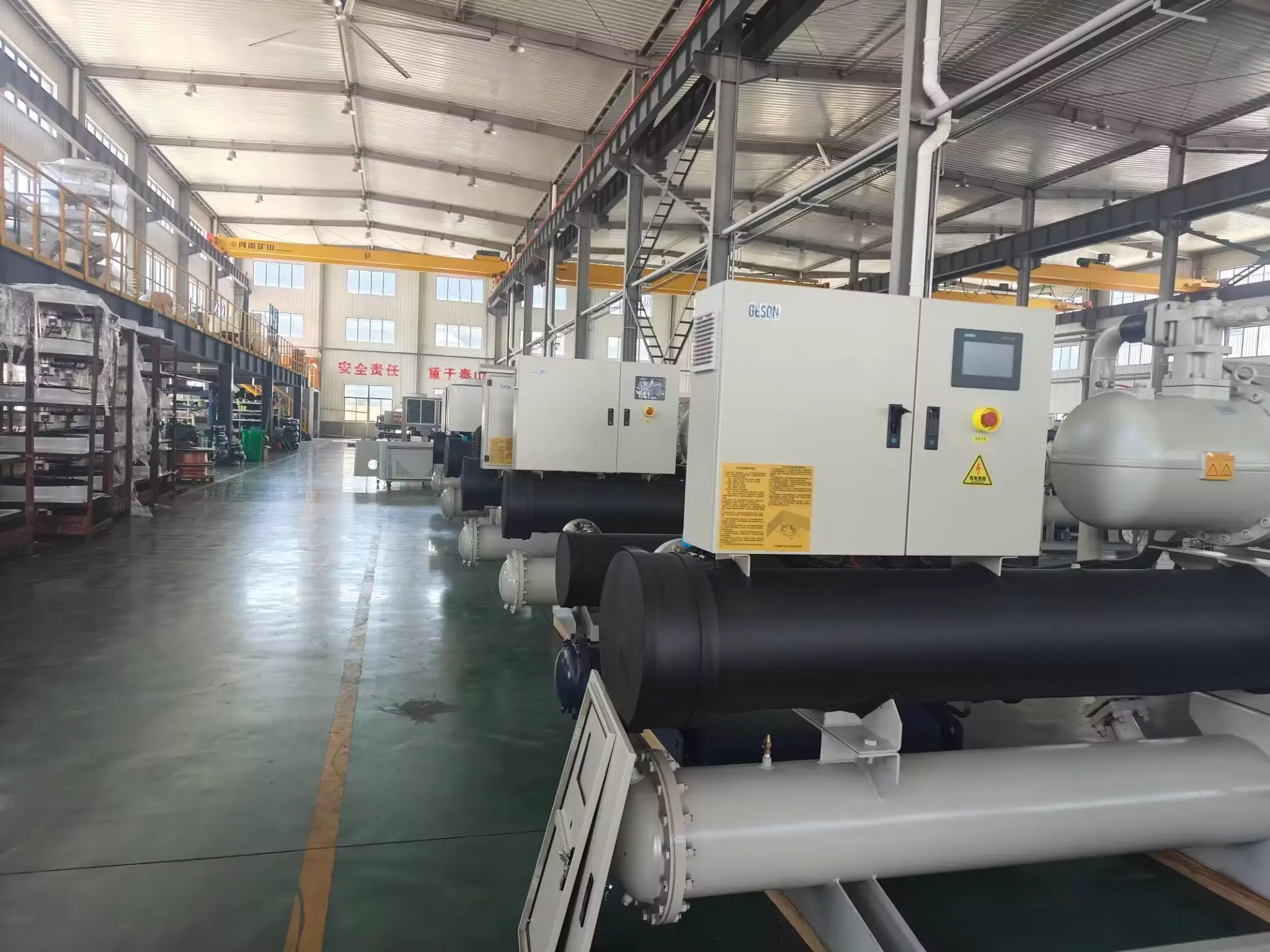
MANUFACTURING SYSTEM REVIEW
The manufacturer review translates the project operating point into an equipment configuration and a clearly allocated factory/site supply scope.
The engineering review records the heat load, temperatures, fluid, heat-rejection condition, electrical supply, operating profile and destination requirements.
The compressor arrangement, heat exchangers, controls, accessories and package boundary are selected for the agreed duty instead of a generic capacity claim.
Assembly, quality checks and run testing are completed for the approved configuration before shipment, with final scope confirmed in the written proposal.
INDUSTRIAL CHILLER MANUFACTURER FAQ
Provide the application, calculated heat load, supply and return temperatures, fluid data, design flow, heat-rejection conditions, electrical supply, operating schedule, installation location and destination requirements. These inputs define the equipment route and model-specific operating point.
Air-cooled systems reject heat to outdoor air and require design ambient, airflow clearance and sound review. Water-cooled systems use a condenser-water loop and an engineered heat sink, often a cooling tower; water quality, wet-bulb condition, pumps and maintenance must be included. The correct choice follows the site rather than capacity alone.
A process chiller controls equipment or production temperature, while an HVAC chiller serves comfort cooling through a building chilled-water system. The application, temperature tolerance, fluid, operating profile, controls and redundancy requirements can therefore be different.
The project proposal can define a coordinated package that includes the selected chiller and approved accessories. Pumps, tanks, controls, heat rejection, piping and commissioning responsibility are confirmed in the written system scope for the particular project.
The quotation should identify the selected model and the stated operating conditions, including capacity and input power at those conditions, fluid data, heat-rejection basis, compressor and heat-exchanger configuration, electrical supply, controls, included accessories and any applicable documentation.
PROJECT-SPECIFIC CHILLER REVIEW
Send the application, heat load, temperatures, fluid, heat-rejection conditions, electrical supply, location and expected operating profile. GESON will help define a suitable industrial cooling route.